Redes Sociales

domingo, 20 de agosto de 2017

The Unity (UMAS) protocol (Part I)

This is the first of a series of entries explaining the configuration protocol used by Schneider-Electric devices, an mainly PLCs (Programmable Logic Controllers) to get configured. This is a proprietary protocol based on the well-known Modbus Protocol. These findings have been obtained through reverse engineering process and many hours of work.


INDEX

Part I. Introduction, initialization phase, functions codes used in the initialization phase

Part II. Function codes used to read and write memory values from/to memory

Part III. Function codes used to deal with logic programs, and work with the PLC

Part IV. Other extra function codes

Part V. Extra information

Part V. Modicon Premium PLCs specific function codes


INTRODUCTION

Schneider-Electric devices, an mainly PLCs (Programmable Logic Controllers) are able to understand a number of Industrial Protocols (Modbus, Bacnet, Ethernet-IP, Canopen, etc). However, in order to be configured they use a proprietary protocol which is based on the Modbus Protocol. During the last year I have been researching on it, and in this set of articles I will explain all I have found about this protocol.

This research process was performed at the CICLAB Laboratory of the University of Leon and thanks to the support of the SUPPRESS group of this University.

As I have not found this proprietary protocol explained anywhere I think this set of articles can be very useful to understand how the Schneider-Electric PLCs and Schneider-Electric SCADA and engineering software (Unity Pro) communicate.

The protocol (which I will call UMAS based on the name of the DLLs and JAR files used to handle it), is based on the old Xway Unite protocol, used by old Telemechanique PLCs, which is well explained here.

Umas protocol is used to configure and monitor the Schneider-Electric PLCs. It is based on the well-known modbus protocol and uses one of the reserved Function Codes specified in the Annex A of the Modbus Protocol Specification (Function Code 90 or 0x5A in hexadecimal).

Actually Wireshark detects this traffic as Modbus with Function Code 90:

The following is the PDU structure of a Modbus request or response:

When Schneider-Electric PLCs receive a modbus packet, it checks if the Function Code is 0x5A and if so, some specific libraries are used, othewise, the modbus request is treated normally, returning or modifying the specified register(s) or coil(s) of the PLC.

The Function Code of the Modbus protocol indicates the PLC what does the following (in the same packet) data mean, what it is for and how to treat it. The Modbus Protocol Specification explain the meaning of 21 different Function Codes. However, in its annex A, it mentions that a total of 11 new Function Codes are reserved for a future use.

The UMAS protocol uses one of these reserved function codes, Function Code 90 (or 0x5Ah) both for the requests to and replies from the PLC. It is little-endian which is strange as modbus is big-endian and it is based in modbus.

Metodology followed

To reverse engineer this protocol I have had a series of sources. Most of my knowledge has been obtained from real UMAS traffic. I passed many hours researching on UMAS traffic and as someone said... "after a period of time you start finding patterns".

Another source of information was the different PLC Firmware versions that can be downloaded from the Schneider-Electric website. Newest firmware versions are digitally signed but older ones are simply ZIP files which in some cases include JAR files with parts of a UMAS handling library.

Finally a third source of information were the DLL files used by the Unity Pro software, although they were never decompiled or hacked.

The UMAS Packet

The UMAS Packet starts with a 16 bit field that Specify a "UMAS Function Subcode", followed by a variable number of bytes which confirm the UMAS packet payload:

In my research work I have found 28 different "UMAS codes" and in most cases I could identify what was their function. The following is the list of UMAS function codes found:

  • UMAS Function Code 0x01 - INIT_COMM: Initialize a UMAS communication
  • UMAS Function Code 0x02 - READ_ID: Request a PLC ID
  • UMAS Function Code 0x03 - READ_PROJECT_INFO: Read Project Information
  • UMAS Function Code 0x04 - READ_PLC_INFO: Get internal PLC Info
  • UMAS Function Code 0x06 - READ_CARD_INFO: Get internal PLC SD-Card Info
  • UMAS Function Code 0x0A - REPEAT: Sends back data sent to the PLC (used for synchronization)
  • UMAS Function Code 0x10 - TAKE_PLC_RESERVATION: Assign an "owner" to the PLC
  • UMAS Function Code 0x11 - RELEASE_PLC_RESERVATION: Release the reservation of a PLC
  • UMAS Function Code 0x12 - KEEP_ALIVE: Keep alive message (???)
  • UMAS Function Code 0x20 - READ_MEMORY_BLOCK: Read a memory block of the PLC
  • UMAS Function Code 0x22 - READ_VARIABLES: Read System bits, System Words and Strategy variables
  • UMAS Function Code 0x23 - WRITE_VARIABLES: Write System bits, System Words and Strategy variables
  • UMAS Function Code 0x24 - READ_COILS_REGISTERS: Read coils and holding registers from PLC
  • UMAS Function Code 0x25 - WRITE_COILS_REGISTERS: Write coils and holding registers into PLC
  • UMAS Function Code 0x30 - INITIALIZE_UPLOAD: Initialize Strategy upload (copy from engineering PC to PLC)
  • UMAS Function Code 0x31 - UPLOAD_BLOCK: Upload (copy from engineering PC to PLC) a strategy block to the PLC
  • UMAS Function Code 0x32 - END_STRATEGY_UPLOAD: Finish strategy Upload (copy from engineering PC to PLC)
  • UMAS Function Code 0x33 - INITIALIZE_UPLOAD: Initialize Strategy download (copy from PLC to engineering PC)
  • UMAS Function Code 0x34 - DOWNLOAD_BLOCK: Download (copy from PLC to engineering PC) a strategy block
  • UMAS Function Code 0x35 - END_STRATEGY_DOWNLOAD: Finish strategy Download (copy from PLC to engineering PC)
  • UMAS Function Code 0x39 - READ_ETH_MASTER_DATA: Read Ethernet Master Data
  • UMAS Function Code 0x40 - START_PLC: Starts the PLC
  • UMAS Function Code 0x41 - STOP_PLC: Stops the PLC
  • UMAS Function Code 0x50 - MONITOR_PLC: Monitors variables, Systems bits and words
  • UMAS Function Code 0x58 - CHECK_PLC: Check PLC Connection status
  • UMAS Function Code 0x70 - READ_IO_OBJECT: Read IO Object
  • UMAS Function Code 0x71 - WRITE_IO_OBJECT: WriteIO Object
  • UMAS Function Code 0x73 - GET_STATUS_MODULE: Get Status Module

Function codes

Requests and responses

First of all we need to keep in mins that this is a request/response protocol. Function Codes are only sent in request message (generally sent from engineering PCs and SCADAs, but that could also been sent by PLCs themselves if working in a master/slave scenario).

Response do no carry the function code and only carry the response code. Therefore the UMAS packet structure would be the following:

    [ TCP Packet ] - [ Modbus Header ] - [5A] - [ UMAS CODE (16 bit) ] [ UMAS PAYLOAD (Variable) ]

All UMAS Responses have a similar structure as well:

    [ TCP Packet ] - [ Modbus Header ] - [5A] - [ RETURN CODE (16 bit) ] [ UMAS PAYLOAD (Variable) ]

The return code can have two possible values:

 0x01 0xFE - Meaning OK
 0x01 0xFD - Meaning Error


UMAS Function Code 0x01 - INIT_COMM

Request

The request message sent to the PLC has no payload. Therefore the 0x01 request message is as simple as:

       [ TCP Packet ] - [ Modbus Header ] - [5A] - [ 00 01 ] 

or 
       [ TCP Packet ]- [ Modbus Header ] - [5A] - [ 00 01 00]

This is a very simple message (surely the simplest one). It can be seen like this in Wireshark:

If we follow the UNITE protocol documentation, the last "00" could be the "Category Code". However the similarities between both protocols are not frequent, so, this is only a guess.

Note: It's important to note that the UMAS Payload first byte (00 in the previous example), can be different in newer firmware versions. The image example was taken from a Schneider Electric PLC running a 2.10 Firmware version.

This 0x01 message can be sent anytime after the connection is established. It requests some information from the PLC.

Response

The response from the PLC to a 0x01 request depends on wether the PLC is currently "reserved" or not. When a engineer connects to a PLC it automatically "reserves" its use so that no other engineer con connect simultaneoulsy to the PLC. As we will see, this feature can be easily broken.

If the PLC is not currently reserved, the response from the PLC is the following:

As it can be seen, the response informs us about the maximum frame size (bytes "fd 03" - meaning 1022 bytes), the firmware version (bytes "10 02" - meaning firmware version 2.10), followed by 9 bytes that store an internal code and the owner's name size, in this situation, "0".

If the PLC is currently reserved, apart from the whole previous payload, a variable number of bytes is responded, storing the Client_ID Name. The following 0x01 response come from a reserved PLC:

As it can be noted, frame size, firmware version, remains unaltered but the 32-bit internal code has changed and the following fileds have changed. oOners's name has become "OWNED" and owner's name size is now 5 for the 5 letters of "OWNED".

Therefore, the structure of this response message is the following:

       [ TCP Packet ] - [ Modbus Header ] - [5A] - [ Error Code (16bit) ] - [ Max frame Size (16bit) ] - [ Firmware Version (16 bit) ]
       [ Unknown 1 (32 bit) ] - [ Unknown 2 (32 bit) ] - [ Client name length (8 bit) ] - [ Client Name (variable) ]

Note: The PLC Reservation process will be explained later on Function Codes 0x10 and 0x11. The reason why this internal code has changed is explained there.


UMAS Function Code 0x02 - READ_ID

Request

This request allow Schneiders's Unity Pro to discern what's the device it is connecting to. This request can be sent any time during the connection. It's actually the first request sent by Unity Pro int teh connextion start process (which will be explained later).

The request message sent to the PLC has no payload. Therefore the 0x02 request message is as simple as:

       [ TCP Packet ] - [ Modbus Header ] - [5A] - [ 00 02 ] 

For this simplicity, no image will be added showing a 0x02 request.


Response

This is an example of response message:

The response from the PLC allows Unity Pro to know the device name (“BMX P34 2020”) in this case, with this text's length (“0C – 12 in this case), the PLC firmware version (2.10), the Ir (8), the HwId (“06 01 03 01”) and the FwLoc (“00 00 00 00”). We know this information because it is also sent during an FTP connection during a DINF command reply.

Therefore the 0x02 command response has the following structure:

       [ TCP Packet ] - [ Modbus Header ] - [5A] - [ Response Code (16) ] -  [ PLC Family (8) ] - [ PLC Type (8) ] - [ PLC ID (16) ] -  
       [ PLC Model(16) ] -  [ Unknown (16) ] - [ Firmware version (16) ] - [ Patch version (16) ] - [ IR /FWVer (16) ] - [ HwId (16) ] -
       [ FwLOC (16) ] - [ Deive name text length (8) ] - [ Device name (variable) ] - [ # of Memory banks ] - [ Memory bank 1 (64)]
       ...
       [Memory bank N (64 bits) ] 

Explanation:

  • Error Code - As mentioned earlier this 16 bit value can be 0x00FD (Error) or 0x00FE (OK)
  • PLC Family (1 byte). In this case value 05 means Modicon. This information was taken from Unity DLL.
  • PLC Type (1 byte). In this case value 30 means odicon M340, BMX P342020. I don't have a list of PLC types. This information was taken from Unity DLL.
  • PLC ID. (2 bytes). Unknown meaning. This information was taken from Unity DLL.
  • PLC Model (2 bytes). In this case "00 00". This information was taken from Unity DLL.
  • Unknown (2 bytes). 2 bytes which remain unknown. Further investigation will probably shed some light into these values.
  • Firmware Version Internally named "Prod Version". This 16 bit value store in reverse order the firmware version of the PLC 0x1002 means V2.10. Different version values have been checked 0x7002 means v2.70, 0x9002 means v2.90, etc.
  • Patch Version. 16 bit field that informs about the patching level inside a firmware version
  • The Ir 16 bit value has an unknown meaning for me. I know its name from the DINF response during a FTP connection
  • The HwId 32 bit value has an unknown meaning for me. I know its name from the DINF response during a FTP connection
  • The FwLoc 32 bit value has an unknown meaning for me. I know its name from the DINF response during a FTP connection. Probably firmware can be store in different locations in PLC's memory.
  • Device type text length is the number of bytes coming in the next field. In this case "0c" meaning 12 bytes.
  • Next bytes retrieve the PLC type. In this case it's a Schneider Electric's Modicon M340 (internally coded as BMX P342020).
  • # Memory banks. 1 byte that informs how many memory banks the PLC has. The SD Card is considered a Memory bank (that's why in this case the value is 2).
  • Memory bank 1 (8 bytes).
  • Memory bank 2 (8 bytes).

Note: Each memory bank 64 bits fields has the following structure of fields:

       [ Bank type (8) ] - [ Folio (8) ] - [ Status (16) ] - [ Size (32) ] 

Note: Bank Type can be 01 for PLC memory or 04 for SD Card. Other possible value (not tested) would be for Memory bank slots


UMAS Function Code 0x03 - READ_PROJECT_INFO

Request

The read project info request has a 8 bit subcode value meaning which project information needs to be read. The function 0x03 request message has the following structure:

       [ TCP Packet ] - [ Modbus Header ] - [5A] - [ 00 03 ] - [ Subcode ] 

Subcode is an 8 bit value and only values 00, 01, 02, 03 and 04 have been seen. Response

The “00 03 00” request allows Unity to get information about the project that's currently running on the PLC. The response from the PLC is similar to the following:

We still don't know what first 9 bytes mean, but they are sent twice, so this information must be important.

After them, the project creation time and date is sent (again twice), finally the PLC send the version number and the project name with its text's size.

These bytes are also found in the APX file (which will be explained later) in offset 29Ch. You can find a complete explanation of the APX file structure in [this link].

Therefore the response stucture is the following:

       [ TCP Packet ] - [ Modbus Header ] - [5A] - [ Response Code (16) ] -  [ Unknown (9 bytes) ] -  [ Unknown 2 (9 bytes) ] - 
       [ Modification date (8 bytes) ] -  [ Modification date Rep (8 bytes) ] - [ Project Version (16) ] - [ Unknown (16) ] - 
       [ Project Name length (8) - [ Project name (variable) ] 

Note:

The modification date, which is sent twice can be splitted in two fields (modifcation time and modifcation date). Modification time is a reverse translation of values. In the example the 4th (0e) is 14 (or 2 in the afternoon). 24 is 36 in decimal, and 37 y 55 dec. The value 04 is unknown. On regards to the date e0 07 hex is 2016 dec, 02 11 is 11th of february. The date when this logic was uploaded to the PLC

After sending a 00 03 00 request, generally a “00 03 04” request is sent. This request ask for the different Objects stored in the PLC memory. A response like the following is replied:

In this response, after the response code (00FE in this case), come 9 blocks of 12 bytes. with the following structure:

  • Response code (16 bit).
  • # of blocks (8 bits)
  • Block 1 mNb (32 bits). This is the size of the object
  • Block 1 mBase (16 bits). This is the memory base
  • Block 1 mBlock (16 bits). This is the memory block. 0x2a are System bits, 0x2b are system words, 0x2c, etc.
  • Block 1 mOffset (32 bits). This the memory position of the beginning of the block.
  • Block 2 mNb, mBase, mBLock and mOffset. ...
  • Block N mNb, mBase, mBLock and mOffset.

In the example above 9 objects are stored in the PLC (actually only 5). Object 1 is 128 bytes long, starting ofrom position 0 of memory block 0x2a (System bits or coils and with offset 00004. The other object maintain the same structure.

We tried to send requests with another number after “00 03”. Only three of them replied:

  • “00 03 01” → Replied with 60 unknown bytes
  • “00 03 02” → Replied with 77 unknown bytes
  • “00 03 03” → Replied with 67 unknown bytes. Part of the information replied here is the same when requesting a 0x20 message on block 30


UMAS Function Code 0x04 - READ_PLC_INFO (GETPLCSTATUS)

During a Unity pro connection, the “00 04” request is sent every 0.3 seconds. It helps both Unity Pro and the PLC to keep the connection alive.

This is an example of a 0x04 message response from the PLC:

After the response code, the three first bytes are ignored by the PLC (at least in the implementation I reversed). So in the example above, bytes with value "02 86 80" are ignored. The next byte is the number of 32-bit blocks read (in this case 6 blocks). So, the first block is "48 ce 01 01", the second is "20 6e 00 18" and so on.

For every block, values are resversed (First byte last, and last byte first). A variable named mAppliCheckSum is calculated with the sum of the reverse values of blocks 3 and 4 (in the example this checksum would be 0x18906e20+0x18906e20). This is a checksum value used to check if the PLC is legitimate or not.

The following bytes are mostly unknown. The could probably some system bits and words. We still don't know which ones.

What we know is that the 6th byte from the end let us know if the PLC is running or not. In that byte, the bits 7 and 8 let us know if the PLC is on or off. If the PLC is off bits 7 and 8th are 0-1 and if the PLC is on, the bits are 1-0. Therefore if that byte is 1 (like in the example) the PLC is off and if the byte is 2, the PLC is on and running.

Requests “00 01”, “00 02”, “00 03” and “00 04” allow Unity to fill this following Unity's dialog box:


UMAS Function Code 0x06 - READ_CARD_INFO

A request “00 06 00” allows Unity Pro to know what specific SD Card is inserted in the PLC.

The response from the PLC informs Unity about the specific model of SD card and internal info:

After the error code bytes, there are 6 bytes which still remain unknown. After them next byte is the length of the SD Card name. and the following bytes are a null-terminated string with the SD Card name.

This is the structure of this response:

       [ TCP Packet ] - [ Modbus Header ] - [5A] - [ Response Code (16) ] -  [ Unknown (6 bytes) ] - 
       [ SD Card name length (8 bytes) ] -  [ SD Card name (variable) ] 


UMAS Function Code 0x0A - MIRROR/REPEAT

This request may have any kind of sinchronyzation purpose, but it's not very clear to me. This message is sent during the initialization process (which will be explained later) and the PLC just replies with the same payload it was sent in the request.

The following is a UMAS MIRROR request:

...and this is the response received from the PLC.

As it can be seen, the payload is sent back in the next reply from the PLC. The UNITE protocol has a very similar message (named MIRROR, but with a different Function Code). For UNITE, this message purpose is stated to be "to test the correct routing of data between two communicating devices. It is also used for carrying out performance measurements."


UMAS Function Code 0x10 - TAKE_PLC_RESERVATION

This message enables a client (Unity Pro - or an attacker) to partially or completely reserve the functions of a PLC. After this message is sent, if other client (Unity Pro) tries to connect to the PLC (by sending, among others, this message), the PLC responds with an error message.

The following is an example of this message:

The structure of this message is the following:

       [ TCP Packet ] - [ Modbus Header ] - [5A] - [ 00 (by now) ] - [ 10 ] - [ Unknown 1 (32 bit) ] -
       [ Client name length (8 bit) ] - [ Client Name (variable) ]

Once a client reserves a PLC giving a client name, next 0x01 request will respond with the client name given during the reservation process, as can be seen in the following image:

The first message is a 0x01 response message received from the PLC, when it has not been reserved yet. Then a 0x10 TAKE_PLC_RESERVATION message is sent. When another 0x01 message is sent, the PLC responds with the third message in this image. It can be stated, the unknown value passed in the TAKE_PLC_RESERVATION is returned in the 0x01 ID message.


UMAS Function Code 0x11 - RELEASE_PLC_RESERVATION

This request is as simple (“00 11”) as its reply (“00 FE”), which is an OK.

It's used by a client to release the PLC reservation. After this message any other client will be able to reserve the PLC again.


UMAS Function Code 0x12 - KEEP_ALIVE

This request is as simple (“00 12”) as its reply (“00 FE”), which is an OK.

We think it is a simple “I'm still here”, and that it's sent when a period of milliseconds expire with no message sent by Unity.

In other words, it's a keep-alive message.


This is all for today. In part II we'll talk about other interesting Function Codes that can be used to read and write values directly to/from the PLC.

miércoles, 19 de julio de 2017

Windows OS version from Major & Minor numbers

Sometimes during an audit you need to determine what's a specific System. Sometimes it's possible to obtain informacion y some SMB traffic is found, but if not, you can find some "BROWSER" traffic:

Sometimes there's no info available. In this cases one can determine the OS that sent this traffic by looking is Major & Minor numbers:

Operating System Version NumberMajor NumberMinor Number
Windows 95 OEM Service Release 1 (95A) 4.00.95040
Windows 95 OEM Service Release 2 (95B) 4.00.111140
Windows 95 OEM Service Release 2.1 4.03.1212-121440
Windows 95 OEM Service Release 2.5 C 4.03.121440
Windows 98 4.10.1998410
Windows 98 Second Edition (SE) 4.10.2222 A410
Windows Millenium Beta 4.90.2476490
Windows Millenium 4.90.3000490
Windows NT 3.1 3.10.528310
Windows NT 3.5 3.50.807350
Windows NT 3.51 3.51.1057351
Windows NT 4.00 4.00.138140
Windows NT 5.00 (Beta 2) 5.00.151550
Windows 2000 (Beta 3) 5.00.203150
Windows 2000 (Beta 3 RC2) 5.00.212850
Windows 2000 (Beta 3) 5.00.218350
Windows 2000 5.00.219550
Windows XP (RC 1) 5.1.250551
Windows XP 5.1.260051
Windows XP, Service Pack 1 5.1.2600.1105-110651
Windows XP, Service Pack 2 5.1.2600.218051
Windows XP, Service Pack 3 5.1.260051
Windows .NET Server interim 5.2.354152
Windows .NET Server Beta 3 5.2.359052
Windows .NET Server Release Candidate 1 5.2.366052
Windows .NET Server 2003 RC2 5.2.371852
Windows Server 2003 (Beta?) 5.2.376352
Windows Server 2003 5.2.379052
Windows Server 2003, Service Pack 1 5.2.3790.118052
Windows Server 2003 5.2.3790.121852
Windows Home Server 5.2.379052
Windows Longhorn 6.0.504860
Windows Vista, Beta 1 6.0.511260
Windows Vista, Community Technology Preview 6.0.521960
Windows Vista, TAP Preview 6.0.525960
Windows Vista, CTP 6.0.527060
Windows Vista, CTP 6.0.530860
Windows Vista, CTP (Refresh) 6.0.534260
Windows Vista, April EWD 6.0.536560
Windows Vista, Beta 2 Preview 6.0.538160
Windows Vista, Beta 2 6.0.538460
Windows Vista, Pre-RC1 6.0.545660
Windows Vista, Pre-RC1, Build 5472 6.0.547260
Windows Vista, Pre-RC1, Build 5536 6.0.553660
Windows Vista, RC1 6.0.5600.1638460
Windows Vista, Pre-RC2 6.0.570060
Windows Vista, Pre-RC2, Build 5728 6.0.572860
Windows Vista, RC2 6.0.5744.1638460
Windows Vista, Pre-RTM, Build 5808 6.0.580860
Windows Vista, Pre-RTM, Build 5824 6.0.582460
Windows Vista, Pre-RTM, Build 5840 6.0.584060
Windows Vista, RTM 6.0.6000.1638660
Windows Vista 6.0.600060
Windows Vista, Service Pack 2 6.0.600260
Windows Server 2008 6.0.600160
Windows 7, RTM 6.1.7600.1638561
Windows 7 6.1.760161
Windows Server 2008 R2, RTM 6.1.7600.1638561
Windows Server 2008 R2, SP1 6.1.760161
Windows Home Server 2011 6.1.840061
Windows Server 2012 6.2.920062
Windows 8 6.2.920062
Windows Phone 8 6.2.1021162
Windows Server 2012 R2 6.3.920063
Windows 8.1 6.3.920063
Windows 8.1, Update 1 6.3.960063
Windows 10 10.0.10240100
Windows Server 2012 R2 6.3.960063

CVE 2017-6017 Video Demo

At last I've ready a video demo of the vulnerability I found last year in the PLC Modicon M340. It was eventually catalogued as:

Other vulnerability databases mentioned it as well:

Ok, then, this is the demo video of the vulnerability (https://www.youtube.com/watch?v=9rz4rI82dWM):

This is very dangerous because an attacker could turn off very easily any of the more than 600 modicon devices currently accesible in internet:

For more information about this vulnerability, visit my previous entry in this blog talking about it.

I currently have an exploit both in python and Ruby, will publish them once the accessible vulnerable devices in shodan go below 100.

Meanwhile, there are many other toys waiting!!

miércoles, 14 de junio de 2017

Key points taken from the Industroyer/CrashOverride malware

I will not spread too much. After reading the CrashOverride report by Dragos (Good Job!!), some points show to be very clear:

  • It's not a malware for espionage purposes. There's no data exfiltration function in the malware.
  • It's more likely to be a destroyer malware (thus the Industroyer name), as there's a wiper module that "renders unusable" the systems where it run.

  • It has been clearly showed that this was the malware that caused the power disruption in Ukrayne in December 2016.
  • In a context of war in Ukrayne, it seems pretty clear who were the developers of CrashOverride.
  • This piece of malware relays on 4 industrial protocols to attack the power plant (IEC104, IEC101, IEC61850 and OPC-DA)
  • After Dragos and ESET reports it appears that, appart from the main team, a second team helped in developing the protocol modules
  • The malware looked and removed a specific type of industrial logic projects. The projects written with ABB PCM 600. It's very clear the knew what they were doing. They knew perfectly the plant and its processes
  • The strategy followed by the attackers was a little bit naive. It just sent values to PLC registers, for opening breakers, de-energizing thus the power plant.
  • However, if the infected system is turned down, an operator will be able to recover the power plant energy very quickly.
  • The malware did not have spreading features and the only way to persist was modifying a running service (svcdefrag) so that it can persist between restarts. However this is a little bit naive perstance method. It wasn't their purpose to persist too much time...
  • Strange enough, malware samples were compiled at 2:30 of December 18th (surely a fake time) while they were used on the attacks just before midnight of December 17th in Ukraine. This apparent inconsistency can be explained if the malware was compiled three time zones before the ukraine's one.
  • Another point that show that it was specially tailored for a specific power plant is that it attacked a specific Siemens protective asset (a Siemens Siprotec relay). Unfortunately since July 2015 these device lack a vulnerability that remains them unsable. Although a firmware update was published to fix this issue, clearly the ukrainian power plant did not fix hteir security problems.

To summarize:

It seems a tailored malware for specific power plant that was not intended to remain undiscovered. It was developed quickly and sent to the victim systems just a few menutes after being compiled. It was probably just a proof of concept and only the specific protocol modules could be used in future attacks.

The malware purpose was not industrial espionage but destruction. In a context of war between Russia and Ukraine and given that it seems to have been compiled two-three time zone east of Ukraine, it seems clear where this malware come from.

viernes, 26 de mayo de 2017

Industrial protocol wireshark dissectors

A list of industrial protocols and their wireshark dissectors to understand them a little bit better:

  1. CoAP --> Protocol Draft --> Wikipedia entry --> Wireshark dissector
  2. HART-IP --> Wikipedia entry --> Wireshark dissector
  3. GOOSE (IEC61850) --> Detailed analysis --> Wireshark dissector
  4. SV (IEC61850) --> Wireshark dissector
  5. Modbus/TCP --> Modbus specification --> Wireshark dissector
  6. OPC DA --> Wikipedia entry --> wireshark dissector
  7. Fieldbus HSE --> Detailed analysis --> Wireshark dissector
  8. IEC 104 --> Wikipedia entry --> Wireshark dissector
  9. Ethernet POWERLINK (EPL) --> Wikipedia entry --> Wirehark dissector
  10. Siemens S7 --> Wikipedia entry --> More info --> Wireshark dissector --> Siemens 300/400
  11. MMS (IEC61850) --> Wirehsark dissector
  12. OPC UA --> Some info --> Wireshark dissector
  13. Omron FINS --> https://github.com/wireshark/wireshark/tree/master/epan/dissectors/packet-omron-fins.c
  14. openSAFETY --> https://github.com/wireshark/wireshark/tree/master/epan/dissectors/packet-opensafety.c
  15. EGD (Ethernet Global Data)--> https://github.com/wireshark/wireshark/tree/master/epan/dissectors/packet-egd.c --> GE Fanuc
  16. DNP3 --> http://github.com/wireshark/wireshark/tree/master/epan/dissectors/packet-dnp.c
  17. Sinec H1 --> https://github.com/wireshark/wireshark/tree/master/epan/dissectors/packet-h1.c
  18. Profinet --> https://github.com/wireshark/wireshark/tree/master/plugins/profinet/
  19. EtherCAT --> https://github.com/wireshark/wireshark/tree/master/plugins/ethercat/
  20. SERCOS III --> https://github.com/wireshark/wireshark/tree/master/epan/dissectors/packet-sercosiii.c
  21. RTPS --> https://github.com/wireshark/wireshark/tree/master/epan/dissectors/packet-rtps.c
  22. TTEthernet --> https://github.com/wireshark/wireshark/tree/master/epan/dissectors/packet-tte.c
  23. CDT --> https://github.com/wireshark/wireshark/tree/master/epan/dissectors/packet-cdt.c
  24. EtherNet/IP --> https://github.com/wireshark/wireshark/tree/master/epan/dissectors/packet-etherip.c
  25. CIP --> https://github.com/wireshark/wireshark/tree/master/epan/dissectors/packet-cip.c
  26. CIP Safety --> https://github.com/wireshark/wireshark/tree/master/epan/dissectors/packet-cipsafety.c
  27. DeviceNet --> https://github.com/wireshark/wireshark/tree/master/epan/dissectors/packet-devicenet.c --> Allen-Bradley
  28. BACnet --> https://github.com/wireshark/wireshark/tree/master/epan/dissectors/packet-bacnet.c
  29. KNXnet / IP --> https://github.com/wireshark/wireshark/tree/master/epan/dissectors/packet-knxnetip.c
  30. Lontalk --> https://github.com/wireshark/wireshark/tree/master/epan/dissectors/packet-lon.c --> LonWorks-
  31. CANopen --> Wikipedia entry --> Wireshark dissector
  32. SAE J1939 --> https://github.com/wireshark/wireshark/tree/master/epan/dissectors/packet-j1939.c --> CAN
  33. USITT DMX512-A --> https://github.com/wireshark/wireshark/tree/master/epan/dissectors/packet-dmx.c
  34. BSSAP/BSAP --> https://github.com/wireshark/wireshark/tree/master/epan/dissectors/packet-bssap.c --> Bristol Babcock Inc
  35. Gryphon --> https://github.com/wireshark/wireshark/tree/master/plugins/gryphon
  36. ZigBee --> https://github.com/wireshark/wireshark/tree/master/epan/dissectors/packet-zbee.h

...and of course there are many more left...

lunes, 27 de febrero de 2017

Discovering Tofino Xenon

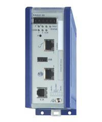
Tofino, apart from a lovely area in the west coast of Canada is a security company that develop products like Tofino Eagle or Tofino Xenon.

The first one is the name of a series of industrial specific routers and the second is an industrial firewall. I was lucky enough to get in contact with a Tofino Xenon and could test its characteristics. The purpose of this post is to capture my experiences with it.

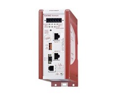
Tofino Xenon

Tofino Xenon is an industrial firewall with state inspection (Stateful firewall - SPI) and Deep Packet Inspection (DPI), that allows the user to filter both Modbus and Ethernet-IP industrial traffic.

Among its characteristics, we should mention that it has two Ethernet 10/100Mbps port and that it works in a transparent on the link layer OSI 2 level, as if it was a bridge device. On the other hand it has the capability to be mounted in a rack through a DIN rail.

The installation is very simple. The manufacturer recommends to install it "just in front of" the PLC or field device that we need to protect and "install a Tofino for each device we need to protect". Taking into account the price of a Tofino Xenon, that's a huge economic effort and not all companies can afford to follow these instructions...

We tested a Tofino in a testbed at the CICLAB laboratory in the University of Leon (in Spain). We connected it, on one Ethernet port to a typical 4 port non-industrial switch and on the other Ethernet port to a Schneider-Electric M340 PLC.

Our objective was to understand how the Tofino Xenon worked. We were not prepared to not even being able to connect to it. Our first difficulty was to discover the MAC address of the Tofino Xenon. We knew that the manufacturer provided a discovery application (Tofino Configurator) that allows to operate with the Tofino Xenon. However we wanted to test on our own, mainly because Tofino Configurator only works for Windows systems... After a few minutes we realized that Tofino Configurator is actually a Java development which is been later compiled into a .exe file.

So, we connected to the Tofino Xenon as explained and tried to discover it on our own. The device itself comes with a sticker which stated the "Tofino ID”. which appeared to be a MAC address. However, the more we tried to "NetDiscover" that mac address (or any other), we didn't find any network device connected to the network:

Eventually we got to find some documentation mentioning that the Tofino ID was actually the MAC address, but this device kept invisble for us. Finally a youtube video ( TV201: Tofino Orientation - https://www.youtube.com/watch?v=gigtan466rA), shed some light into our situation. We then realized that device (as it's stated in the documentation) works at Level 2 OSI, and therefore it never adquires any IP address.

We then realized that Tofino Configurator has a peculiar way of discovering Tofinos:

  1. Tofino Configurator only works if there are two devices (or networks) connected to the Tofino, one to each Ethernet Port.
  2. With this configurator, it sends a UDP packet simulating to be a device connected to one of the ethernet ports, and that packet is sent to another device which is in the network connected to the other Ethernet port of the Tofino Device. This UDP packet will be sent to the 6689/UDP port of the "destination device".

    Tofino Xenon discovery performed with Tofino Configurator

  3. Tofino Xenon detects this packet and returns a new UDP packet to the originator, apparently from (and therefore faking) the address of the UDP destinee. However is actually Tofino Xenon who is replying. This UDP request never arrives to the destination.
  4. When this UDP packet is returned, a TCP conversation starts between our computer and the the Tofino Xenon.

The following is a Wireshark screenshot of the whole process traffic:

As you can see from our IP address (10.10.13.136) a UDP packet is sent (packet 24) to a device which is located on the other network (10.10.13.200). This IP address belongs to a computer connected directly to the Tofino on the other Ethernet port.

The UDP packet is sent against port 6689 of the destinee. As there's nothing listening on port 6689 of the destination computer, this returns an error ICMP reply (packet 25) -in black-, but, at the same time, the originator receives as well a UDP packet (packet 26), apparently from the same destination IP and from the port 65002. Packet 26 is actually sent by the Tofino Xenon, when it detects a the previous UDP packet which travel between its ethernet ports. This UDP packet is clearly parsed by the tofino Xenon, which clearly shows, it's a stateful firewall.

Tofino Configurator sends next, from the origin IP (10.30.13.136), a second -slighly longer- UDP packet (packet 30), which is never replied by the Tofino Xenon.

Finally Tofino configurator starts a TCP conversation (packets 36 on) where the Tofino Xenon configuration information is interchanged.

Information interchanged next through a TCP (encrypted) connection

Our first objective was trying to understand the UDP "handshake" sent between Tofino configuration and Tofino Xenon, but we were not able to understand the UDP payload. It sends a 68 byte payload. From thos 68 bytes, bytes 21 to 36 (16 bytes) were always the same, in all discoveries we tried. It could be any license key from the Tofino Xenon.

The rest of the bytes are clearly encoded or even encrypted data (no bytes 00 or FF were found):

We tried to write our own script in order to be able to connect and configure the Tofino Xenon. We used python and Scapy to do it:

Even when we followed the steps previously mentioned, the Tofino Xenon did not reply to the UDP packet on port 6689. We eventually tried to connect a second Tofino Configurator software to try to work in two computers at the same time. And then we realized that we could connect to Tofino Xenon from towo machines at the same time.

Somehow, Tofino Xenon maintains a connection status and the MAC address from the "owner" client of the firewall. It seem to store any kind of state table that stores which MAC address is the "Master", and only this Master has the capabilities of access and modification over the Tofino Xenon configuration.

So to confirm this hypotheses, we resetted the Tofino Xenon. Again, only the first "client" was allowed to configure the Tofino Xenon. It seems that once a "master" takes control of the Tofino, no other device is allowed to even "discover" it (UDP packets to port 6689, do not work any more).

DoS

Another test we performed was to send it a hugh amount of UDP packets to port 6689. We detected that, if Tofino has already been discovered, Tofino simply discarded and relied UDP packets to port 6689. But if Tofino had NOT been already discovered and a 6689/UDP packet flooding was performed, a Denial of Service occurred, as no other IP could discover Tofino, because it was working on parsing all malicious UDP packets.

"Pickpocketing" Tofino

Then we deciedd to try to "pickpocket” Tofino Xenon to a legitimate Tofino Configurator who had legitimely discovered it.

We tried hard and harder but we were not able to accomplish this task. Once a UDP to port 6689 passes through Tofino, the device stops replying to any request not coming from the owner/master who has discovered it. Only when we modified/faked our attacking MAC address to be the same of the legitme master could we receive any reply from Tofino.

Next test was to try to understand the “protocol” used between the Tofino Configurator and the Tofino Xenon. We obtained a pcap file with the traffic interchaneg between both of them. We found that:

  • Tofino Xenon comes with an embedded OpenSSH server. it's banner says it's a OpenSSH 6.4 (from 2014)
  • Tofino Configurator uses a library named Ganymed to connect to Tofino Xenon. This library was implemented in 2006.

All the configurator initialization process, the Tofino rules which are sent to the device, the reset process and many other functions offered by Tofino Configurator are performed through encrypted commands sent via SSH.

A second script was implemented with Scapy that emulated that encrypted communication, from a previously obtained pcap file. However, although the connection was established, logically, the encryption key need to be different to the one used in the captured pcap, so we could not continue on this path.

This way, after a promising initial connection establishment, the Tofino cutted of the communication once the key interchanged process was not able to finish properly.

After a number of further tests we realized that the encryption key negotiation was RSA-SSH. We tried to modify the encryption algorithm for this negotiation. As it can be seen in the following capture, the negotiated protocols go in plain text and we could modify them, removing all but "None":

Eventually we discovered that the Tofino Configurator library allows the "None" cyphering algorithm, however Tofino Xenon does not. At this point, we decided to give up in our attempts to compromise Tofino Xenon.

Summary

Tofino Xenon is a secure Industrial Firewall. It includes a number of security features (it is only discovered at level 2 OSI, all communication is performed via SSH, and therefore encrypted, etc). However I wouldn't say it's unbreakable. From our point view, it's been only the lack of time that has stopped us from compromising it. It's not easy, but it does not seem impossible.

Several tests could not be performed:

  • Continue working on the encryption and encryption key negotiation process
  • Decompiling Tofino Configurator in order to understand how the Configurator work

However one possible vulnerability was found, as the device stops responding when it has not been discovered and it's flooded with UDP packet to port 6689. This cannot be considered a vulnerability, as the first step an operator does when installing the Tofino Xenon. And once a PC connects to the Tofino, it cannot be used by other "client" unless it's reset.

Given the price of the device, the manufacturers should have put stronger efforts on securing point like:

  • Not using Java for Tofino Configurator Development
  • Adding more protocol that can be inspected by the firewall
  • Avoid flooding attacks

Surely inside Tofino there's a Linux OS, or maybe a VxWorks OS. But surely it implements a iptables firewall inside it.

From our point of view, it would be much cheaper to implement a industrial firewall using a computer with a well-tested set of iptables rules.

P.S: These tests were performed by the members of the CICLAB Group at the University of León (Juanma, Jacinto, Borja and me).

miércoles, 22 de febrero de 2017

Resource exhaustion vulnerability on Schneider-Electric M340 PLC

Introduction

Past May, while working at the CICLAB laboratory of the University of Leon (Spain), I came across with a vulnerability on the PLC (Programmable Logic Controller) I was working with. For a research paper, which is currently under review, I had to deal with the configuration protocols used by the different PLCs I had in my testbed. The testbed consists of a number of PLCs from different vendors, among them Schneider-Electric.

Schneider-Electric PLCs configuration protocol is an evolution of the well-known modbus protocol, but using only the 0x5A Function Code. This protocol (or subprotocol), named internally "UMAS", has not been publicly specified, and therefore it had to be reverse-engineered.

After decoding this "UMAS" protocol (which I will explain in a future entry of this blog), I tried to send some invalid traffic to test the robustness of the PLCs.

From the Schneider Family of PLCs I had two different models in my testbed, a M580 PLC and a M340 PLC. After several tries, I was not able to compromise the Schneider-Electric M580 PLC, however when tried to send specially crafted UMAS packets to the M340 PLC, I found it stopped replying to ping commands.

This behaviour was tested using three different firmware versions. The M340 PLC seemed vulnerable, even when working with the latest firmware version (V2.70 at the moment).

Schneider Electric was contacted. I sent them an explanation of the problem together with a "pcap" file that showed the problem. Very quickly they let me know they had done their own tests and that it was a real vulnerability. It was finally published as the security notification SEVD-2017-048-02. The ICS-CERT has not released the public advisory yet, but they're on the way.

I must say they have been very very professional.

The Schneider-Electric M340 PLC

Explanation of the vulnerability

As mentioned earlier, this vulnerabilities is based on the modification of a series of legitimate "UMAS" packets sent in a specific order. "UMAS" is a configuration protocol that allows the software clients (Unity Pro and Vijeo Citect among others) to connect, configure and monitor Schneider-Electric PLCs. More than 20 different subfunction codes have been determined. These function codes allow the client to perform different tasks (Check keepalive, start/stop, upload/download strategies, read/write memory, etc).

One of these "subfunction codes" allow the client to "read" from the PLCs memory asking for a number of bytes to be read, starting from an offset of a "Memory block" (specified by a 16 bit number).

These memory blocks store different types of information (unlocated variables, system words, function blocks, etc). Every memory block has a different size (or top offset), depending on the data stored (sometimes it's 0x5B00, sometimes 0x3F00, sometimes 0xF500...). When trying to read memory over the "top offset" of a memory block, the PLC got locked. This happened with different "memory blocks", always that you sent a UMAS_read_memory request reading over the top offset of the block.

That's what, in other words Schneider-Electric explain with the following sentence:

The software does not properly restrict the size or amount of resources that are requested 
or influenced by an actor, which can be used to consume more resources than intended. 

After sending this series of packets, the PLC got freezed and only could be recovered by approaching physically to the device and resetting it manually.

The following image show a wireshark capture at the moment where this packet (#133) is sent. Before the packet is sent the PLC (IP 10.1.0.102) replies to the different requests done by the client (10.8.0.101). It can be seen as well that a few seconds later some ping commands are sent and the PLC do not reply them:

Wireshark capture of the moment of the attack

The vulnerable UMAS packet is shown shadowed, but it can be seen that it requests the offset 0xF503 (while the top offset is 0xF500.

The following image shows the python script written for testing purposes. In the screen of the right the script is launched, in the screen of the right a ping command is running and suddenly it stops showing ping connection (when the exploit packet is finally sent).

Scripts used for the test

Current Situation

Schneider-Electric bundled a number of fixes in a new firmware version (V2.90) which was released on December 21st. However, 2 months after the public release, very few from the currently available Schneider-Electric M340 PLCs are currently protected.

The Schneider-Electric public disclosure of this vulnerability was published a few days ago.

A simple search in shodan for on of the affected devices (looking for "BMX P34 2020") show that more than 700 devices (of this type) are currently accessible to internet and have not been upgraded to the firmware version V2.8 or V2.9.

Shodan capture showing more than 700 vulnerable devices

This means that more than 700 potentially critical devices could be sent offline remotely in a question of seconds. I have an exploit script for metasploit ready, but clearly it will not be publicly released for a few months (or years!).

Acknowledges

The discovery of this vulnerability has been possible by the funding of INCIBE and thanks to the support of the colleagues of the CICLAB Laboratory at the University of León (Jacinto, Juanma and Borja) and the rest of the guys of the IAF.