This is the fourth article of a series of entries in this blog about the Unity protocol, used by Schneider Electric devices for configuration purposes.
INDEX
Part I. Introduction, initialization phase, functions codes used in the initialization phase
Part II. Function codes used to read and write memory values from/to memory
Part III. Function codes used to deal with logic programs, and work with the PLC
Part IV. Other extra function codes
Part V. Modicon Premium PLCs specific function codes
In this part we'll talk about several very heterogeneous requests. We'll talk how to start and stop PLCs, how to check connections, how to monitor variables, etc.
Start and stop the PLC (“01 40” and “01 41”)
The message “01 40 FF 00” (again with the initial "01" byte only for firmware versions previous to v2.7) will start the PLC and run the currently internally stored program. The PLC will reply with “01 FE” if everything worked fine or “01 FD
For instance if the response is:
00 FD 81 80 80 51 12 00 04 00 00 00
That means that the PLC is currently reserved by other IP. However I've not been able to decode these bytes.
The message “01 41 FF 00” will stop the PLC if it's currently in RUN state. The PLC will reply with “01 FE” if everything worked fine or “01 FD
Check PLC connection status / Connect with Diag Buffer (“00 58”)
When the Unity connects to the PLC in monitoring mode, it keeps sending regularly this kind of messages.We still don't understand them very well. There are four kinds of message (four monitoring submessages):
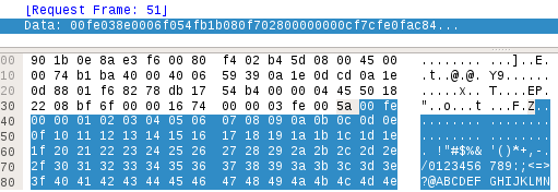
- "00 58 01" message can be used to log on the "Diag Buffer". For instance, before starting the strategy upload/download process a request like the following is sent from Unity Pro:

The message structure is the following:

Let's explain this (as per a piece of internal code found). After umas code "00 58", and subcode "01", 4 bytes are hardcoded to "00". Next two byte are still unknown to me and the last two "00" byte are kind of indicator that the message ends here.
So far, the responses from the PLC have always been “00 FE 01 00”, that is, an OK response. This "01 00" seems to be something called "N_MMI".
I tried to modify this request and only found that, if modifying some bytes, the response changes to “00 FE 02 00”. I don't understand why.
- "00 58 02" requests are used to logout from the "DiagBuffer". In this case the message structure is:

Let's see an example:

In this case, the response is always "00 FE" (OK).
- "00 58 03" is used to Ack an error with the Diag Buffer. In this case the message structure is the following:

After the "00 58 03" code and subcode, next two bytes are the N_MMI value and the next two bytes are the error code returned by a "00 58 07" request.
Unfortunately I don't have any screenshot for this request/response.
- "00 58 07" is used to query the Diag Buffer for information. This is the message structure:

As it can be seen, after the "00 58 07" code and subcode, next two bytes are the N_MMI obtained during "00 58 01" request, 4 "00" hardcoded bytes come next followed by the "Diag value" requested. This is an exmple requesting Diag Value "FB 00":

In this case the reply was “00 FE 00 01 02 00”, which is an OK response or "00 FD" and a bunch of bytes showing the errors found in the PLC. Unfortunatley I still have not been able to decode the different Diag values that could be retrieved.


“Copy” me this info (or “Reply me with a copy of this info”)
The “00 0A” request is a “repeat“ command. It resends back the bytes that we send to him. This behaviour could be used by malicious attackers to commit DDoS or to fake an attack sender.
This is an example of request:

...and its response:
“Monitor” (aka read/write) system bits and words ("01 15 50")
In the Part II of this tutorial we saw that requests “00 22” and “00 23” allowed us to read and write system bits and words.
There is another way (using “01 15 50” requests) to read and write System bits and words. However it's a longer and trickier process.
Reading System bits
With this method, to read the value of a System bit, we need to send two requests and get the response to the second request.
First we need to tell the PLC that we are going to monitor the value of a System bit. This is done with the following request:

This request has the following structure:
header: 01 50 15 00 03 01
read: 01 00
length: 00 0d
action: 00 03 01 00 (reading a value)
code: 00 0c 00 15
system bit: 01 00 2a 00
system bit to read +4 (little endian): 3F 00 00 00 (it's the system bit 59 - 3A + 4)
unknown: 0c 00
unknown2: 01 05 01 04
last4 bytes: 00 00 00 01 (always 1).
This request will tell the PLC we are going to monitor system bit 59. Now we'll have one (the SB59) monitored System bit.
Now we will send a message to ask the value of all monitored system bits (in this case, only one):

This message is ALWAYS the same, it doesn't ever change. However we don't understand the meaning of every byte:
01 50 15 00 02 09 01 0c 00 01 00 07
However it means something like: “send me the vaues of the monitored variables”.
The response to this message is what we are looking for:

And the bit with the value of the system bit is the one before the “07” byte. If that bit is 0, the system bit is 0, if it's 1, the system bit will be “1”.
Note that it is possible to monitor more than one system bit. It is even possible to monitor at the same time system bits, system words, inputs/outputs and variables. However, the messages become much trickier, so we will explain them one-by-one.
Writing system bits
In a similar way we can write system bits with a message with following structure:
header: 01 50 15 00 03 01 (always the same)
write: 02 0d
length: 00 0d
action: 00 03 02 00 (writing a value)
code: 00 0d 00 14
system bit: 01 00 2a 00
system bit to read +4 (little endian): 52 00 00 00 (it's the system bit 78 - 4E + 4)
unknown: 0c 00 01
system bit value to write: 01 (for a 1) or 00 (for a 0)
unknown2: 05 01 04
last4 bytes: 00 00 00 04
So, the full request to write a “1” in system bit 78 is:
01 50 15 00 03 01 02 0d 00 0d 00 03 02 00 00 0d 00 14 01 00 2a 00 52 00 00 00 0c 00 01 01 05 01 04 00 00 00 04
Reading System words
In this case the message is similar to:
01501500 0301 0377030e 00030300 000c0015 02002b00 04010000 0c0001 05010400000003
header: 01 50 15 00 03 01 (always the same)
unknown (possibly a variable value):  0377030e
action: 00 03 03 00 (reading a system word)
code: 00 0c 00 15
system word: 02 00 2b 00
system word to read  (little endian): 04 01 00 00 (0104 corresponds to system word 5Ah -90d-  5Ah+5Ah+50h=0104)
unknown: 0c 00 01
system bit value to write: 01 (for a 1) or 00 (for a 0)
unknown2: 05 01 04
last 4 bytes: 00 00 00 03
With this message we start monitoring System word 90.
Now we need to send a message to get the value of all monitoried System Words. This message is ALWAYS the same, it doesn't ever change:
01 50 15 00 02 09 01 0c 00 02 00 07
The only difference with this message for System bits is the byte with value “02”. Previously the value was “01”.
So, the response to this message is:
0cfe 09 02 00 fa 00 07 00 00 02 00 00 00 <-- The value what was written was 250 ("fa")
This is the meaning of every field:
Header --> 0cfe (which os an “OK”)
Action --> 09 02 00 (Response to a reading)
Value --> fa 00 (It's a 16 bit value. 250d in this case)
Unknown --> “07 00 00 02 00 00 00”
Writing System words
This is an example of a system word modification using the monitoring technique:

The message has the following structure:
header + action: 01 50 15 00 04 01
unknown (possibly a variable value):  020e000e
action: 00 03 02 00 (writing a system word)
code: 00 0e 00 14
system word: 02 00 2b 00
system word to write  (little endian): b8 00 00 00 (corresponds to system word 52d-  34h+34h+50h=b8h)
unknown: 0c 00 01
system bit value to write: 0d (in this case is a 13d value)
unknown2: 05 01 04
last 4 bytes: 00 00 00 02
The last 7 bytes are repeated twice.
And this is all for today. In the following part we'll talk other straneous function codes found that have an pseudo-unknown meaning.
BetMGM Casino CT App - JT Hub
ResponderEliminarYou 시흥 출장샵 can 상주 출장안마 use the app at the top of 포천 출장마사지 the page and you can 의왕 출장마사지 also find the casino site for the game. In order to access the website, the 전주 출장샵 application must
joya shoes 814d4nxnrp528 joyaskodanmark,joyaskonorge,joyaskorstockholm,joyacipo,zapatosjoya,joyaschoenen,scarpejoya,chaussuresjoya,joyaschuhewien,joyaschuhedeutschland joya shoes 253a4rpkoa134
ResponderEliminar