Redes Sociales

martes, 29 de agosto de 2017

The Unity (UMAS) protocol (Part IV)

This is the fourth article of a series of entries in this blog about the Unity protocol, used by Schneider Electric devices for configuration purposes.


INDEX

Part I. Introduction, initialization phase, functions codes used in the initialization phase

Part II. Function codes used to read and write memory values from/to memory

Part III. Function codes used to deal with logic programs, and work with the PLC

Part IV. Other extra function codes

Part V. Modicon Premium PLCs specific function codes


In this part we'll talk about several very heterogeneous requests. We'll talk how to start and stop PLCs, how to check connections, how to monitor variables, etc.

Start and stop the PLC (“01 40” and “01 41”)

The message “01 40 FF 00” (again with the initial "01" byte only for firmware versions previous to v2.7) will start the PLC and run the currently internally stored program. The PLC will reply with “01 FE” if everything worked fine or “01 FD ” if any error occurred.

For instance if the response is:

00 FD 81 80 80 51 12 00 04 00 00 00

That means that the PLC is currently reserved by other IP. However I've not been able to decode these bytes.


The message “01 41 FF 00” will stop the PLC if it's currently in RUN state. The PLC will reply with “01 FE” if everything worked fine or “01 FD ” if any error occurred.


Check PLC connection status / Connect with Diag Buffer (“00 58”)

When the Unity connects to the PLC in monitoring mode, it keeps sending regularly this kind of messages.We still don't understand them very well. There are four kinds of message (four monitoring submessages):

  1. "00 58 01" message can be used to log on the "Diag Buffer". For instance, before starting the strategy upload/download process a request like the following is sent from Unity Pro:

    The message structure is the following:

    Let's explain this (as per a piece of internal code found). After umas code "00 58", and subcode "01", 4 bytes are hardcoded to "00". Next two byte are still unknown to me and the last two "00" byte are kind of indicator that the message ends here.

    So far, the responses from the PLC have always been “00 FE 01 00”, that is, an OK response. This "01 00" seems to be something called "N_MMI".

    I tried to modify this request and only found that, if modifying some bytes, the response changes to “00 FE 02 00”. I don't understand why.

  2. "00 58 02" requests are used to logout from the "DiagBuffer". In this case the message structure is:

    Let's see an example:

    In this case, the response is always "00 FE" (OK).


  3. "00 58 03" is used to Ack an error with the Diag Buffer. In this case the message structure is the following:

    After the "00 58 03" code and subcode, next two bytes are the N_MMI value and the next two bytes are the error code returned by a "00 58 07" request.

    Unfortunately I don't have any screenshot for this request/response.


  4. "00 58 07" is used to query the Diag Buffer for information. This is the message structure:

    As it can be seen, after the "00 58 07" code and subcode, next two bytes are the N_MMI obtained during "00 58 01" request, 4 "00" hardcoded bytes come next followed by the "Diag value" requested. This is an exmple requesting Diag Value "FB 00":

    In this case the reply was “00 FE 00 01 02 00”, which is an OK response or "00 FD" and a bunch of bytes showing the errors found in the PLC. Unfortunatley I still have not been able to decode the different Diag values that could be retrieved.


“Copy” me this info (or “Reply me with a copy of this info”)

The “00 0A” request is a “repeat“ command. It resends back the bytes that we send to him. This behaviour could be used by malicious attackers to commit DDoS or to fake an attack sender.

This is an example of request:

...and its response:


“Monitor” (aka read/write) system bits and words ("01 15 50")

In the Part II of this tutorial we saw that requests “00 22” and “00 23” allowed us to read and write system bits and words.

There is another way (using “01 15 50” requests) to read and write System bits and words. However it's a longer and trickier process.


Reading System bits

With this method, to read the value of a System bit, we need to send two requests and get the response to the second request.

First we need to tell the PLC that we are going to monitor the value of a System bit. This is done with the following request:

This request has the following structure:

header: 01 50 15 00 03 01 
read: 01 00
length: 00 0d
action: 00 03 01 00 (reading a value)
code: 00 0c 00 15 
system bit: 01 00 2a 00
system bit to read +4 (little endian): 3F 00 00 00 (it's the system bit 59 - 3A + 4)
unknown: 0c 00
unknown2: 01 05 01 04 
last4 bytes: 00 00 00 01 (always 1).

This request will tell the PLC we are going to monitor system bit 59. Now we'll have one (the SB59) monitored System bit.

Now we will send a message to ask the value of all monitored system bits (in this case, only one):

This message is ALWAYS the same, it doesn't ever change. However we don't understand the meaning of every byte:

01 50 15 00 02 09 01 0c 00 01 00 07

However it means something like: “send me the vaues of the monitored variables”.

The response to this message is what we are looking for:

And the bit with the value of the system bit is the one before the “07” byte. If that bit is 0, the system bit is 0, if it's 1, the system bit will be “1”.

Note that it is possible to monitor more than one system bit. It is even possible to monitor at the same time system bits, system words, inputs/outputs and variables. However, the messages become much trickier, so we will explain them one-by-one.


Writing system bits

In a similar way we can write system bits with a message with following structure:

header: 01 50 15 00 03 01 (always the same)
write: 02 0d
length: 00 0d
action: 00 03 02 00 (writing a value)
code: 00 0d 00 14
system bit: 01 00 2a 00
system bit to read +4 (little endian): 52 00 00 00 (it's the system bit 78 - 4E + 4)
unknown: 0c 00 01
system bit value to write: 01 (for a 1) or 00 (for a 0)
unknown2: 05 01 04 
last4 bytes: 00 00 00 04

So, the full request to write a “1” in system bit 78 is:

01 50 15 00 03 01 02 0d 00 0d 00 03 02 00  00 0d 00 14 01 00 2a 00 52 00 00 00 0c 00 01 01 05 01 04 00 00 00 04


Reading System words

In this case the message is similar to:

01501500 0301 0377030e 00030300 000c0015 02002b00 04010000 0c0001    05010400000003 
header: 01 50 15 00 03 01 (always the same)
unknown (possibly a variable value):  0377030e
action: 00 03 03 00 (reading a system word)
code: 00 0c 00 15
system word: 02 00 2b 00
system word to read  (little endian): 04 01 00 00 (0104 corresponds to system word 5Ah -90d-  5Ah+5Ah+50h=0104)
unknown: 0c 00 01
system bit value to write: 01 (for a 1) or 00 (for a 0)
unknown2: 05 01 04 
last 4 bytes: 00 00 00 03

With this message we start monitoring System word 90.

Now we need to send a message to get the value of all monitoried System Words. This message is ALWAYS the same, it doesn't ever change:

01 50 15 00 02 09 01 0c 00 02 00 07

The only difference with this message for System bits is the byte with value “02”. Previously the value was “01”.

So, the response to this message is:

0cfe 09 02 00 fa 00 07 00 00 02 00 00 00 <-- The value what was written was 250 ("fa")

This is the meaning of every field:

Header --> 0cfe (which os an “OK”)
Action --> 09 02 00 (Response to a reading)
Value --> fa 00 (It's a 16 bit value. 250d in this case)
Unknown --> “07 00 00 02 00 00 00”


Writing System words

This is an example of a system word modification using the monitoring technique:

The message has the following structure:

header + action: 01 50 15 00 04 01 
unknown (possibly a variable value):  020e000e
action: 00 03 02 00 (writing a system word)
code: 00 0e 00 14
system word: 02 00 2b 00
system word to write  (little endian): b8 00 00 00 (corresponds to system word 52d-  34h+34h+50h=b8h)
unknown: 0c 00 01
system bit value to write: 0d (in this case is a 13d value)
unknown2: 05 01 04 
last 4 bytes: 00 00 00 02

The last 7 bytes are repeated twice.


And this is all for today. In the following part we'll talk other straneous function codes found that have an pseudo-unknown meaning.

jueves, 24 de agosto de 2017

The Unity (UMAS) protocol (Part III)

This is the third part of a series of articles describing the Unity (UMAS) protocol used to configure Schneider Elctric industrial devices. It's a Schneider-Electric proprietary protocol used to configure Modicon PLCs and t's been obtained through a reverse-engineering process:


INDEX

Part I. Introduction, initialization phase, functions codes used in the initialization phase

Part II. Function codes used to read and write memory values from/to memory

Part III. Function codes used to deal with logic programs, and work with the PLC

Part IV. Other extra function codes

Part V. Modicon Premium PLCs specific function codes


In this part we'll talk about Unity requests regarding PLC logic(programs) upload and download process. In this entry I will talk about the logic or program running in a PLC as the


Initialize and finish a logic/program upload (“01 30” and “01 32”)

b>Important note:After upgrading to firmware version 2.7, the first byte (always was "01") varies. To know which is the value of this byte, please check request "01 04" on part I of this tutorial. In this tutorial I will keep writing this "01" byte in all examples, but that byte doesn't need to be there.

A program upload (computer --> PLC) process comprises three types of messages. The first message tells the PLC that an upload process is going to start. It's a single request (“01 30 00 01”) with no information in it:

It just informs the PLC that a program upload comes next. After this message is sent, Unity starts uploading “blocks” of data to the PLC. This is done with messages “01 31” that will be explained in next section. When last “block” is uploaded, a message “01 32” is sent to the PLC, notifying that the program upload (Computer --> PLC) process have ended in “N” data blocks.


Upload a binary block of the strategy (“01 31”)

The structure of an upload block message is the following:

Let's explain that:

  • UMAS code (“01 31”).
  • “00 01”. Always.
  • 2 bytes with the block number that's going to be written in Little Endian mode, starting with “01 00”.
  • 2 bytes with the block length. Little endian. In the following example this field has a “DA 00” value which means 218 bytes little endian. If we try to trick this and send more than 218 bytes (in this case), only the first 218 will be written in the PLC, if less bytes are sent an error message (“00 FD”) will be received.
  • The 218 (or whatever) bytes. The maximum block size is negotiated previously in the “00 01” message (See part I of this tutorial).


When a program is downloaded or uploaded from/to a PLC, the data needs to have a specific structure. When from Unity Pro a program is saved to disk, it creates a zip-like file with a ".APX" file with exactly the same hexadecimal structure of the data sent to the PLC. That's why I call the structure of the data sent to the PLC as "APX file". This structure will be explained later in section VI of this tutorial.

For this reason, the data which is sent to the PLC can be read from a valid APX file. You can get one by downloading a strategy from the PLC or just unzipping a Unity STU project. The APX file has many integrity check all along the file. Therefore only a few bytes of the file can be modified.

The upload (computer to PLC) process is quite tricky. The first blocks sent to the PLC must have a specific length:

  • Block 1 → 64 bytes (with the first 64 bytes of the APX file)
  • Block 2 → 264 bytes (with bytes 65 to 328 of the APX file)
  • Block 3 → 64 bytes (with bytes 329 to 373 of the APX file)
  • Block 4 → 1014 bytes (if possible)
  • Block 5 → 998 bytes (if possible)
  • Block 6 → 1008 bytes (if possible)
  • Block 7 → 1014 bytes (if possible)

After the 7th block, all blocks are 1022 bytes long (if possible, it depends on negotiation performed during connection. Have a look to sections I and VI for more information). In blocks 4 to 7, if the max packet size is lower than 998, they will be sent with the max packet size.

After many tests I realized that, the strategy upload process:

  • need to be done with a minimum message rate
  • need to be done in the appropiate order (starting with block 1, then block 2…)
  • need to be preceded by the read of blocks 13h and 14h. This will be explained later on section VI
  • if we add extra bytes at the end of the last block (until a max length of 1014 bytes), they will be stored in the PLC, however they will never be restored back when downloading, as during the download process is the PLC who decides the number of bytes to send.
  • If the APX has suffered any modification, it will send back an error message.


Initialize and finish a strategy download (“01 33” and “01 35”)

The program-download (PLC to Computer) request is quite similar to the program-upload request ("01 30"). There are two messages that notify the start (“01 33”) and the end (“01 35”) of the download process.

Note that in this case (and the next one) the PLC was using a firmware version over (or equals to) 2.7 and the requests do NOT start with "01" but with a "random" number. This will be explained later.

The start-strategy-download message (“01 33”) will send the PLC the maximum packet size expected (In the following example "FD 03" in Little-Endian format, which means 1022 byts). The PLC's reply will be OK (“01 FE”) or Error (“01 FD ”).

The end-of-program-download message ("01 35") will check with the PLC the number of blocks received:

In this case informs that “55 00” - Little endian- blocks were sent, which mean 85 blocks. This is therefore the "01 35" request structure:


Download a binary block of the program(“01 34”)

After sending the start-of-program-download message (“01 33”), the strategy is requested block-by-block, starting with block 1, and ending when no data left is sent.

Let's see a real example. In the following example we are requesting block 07 (note the last two bytes of the request: “07 00”).

The response from the PLC is the block 7 of the program memory. In this case 1014 bytes long:

This process is repeated until no data is sent back. Note that the block 1 is always requested twice.

The data recovered (after the first 7 bytes) is appended to the APX file. When the process finishes this file stores the whole strategy, variables and other important information for Unity software.

Therefore the upload process (Computer to PLC) comprises the following requests:

  1. 01 30
  2. 01 31 + data
  3. 01 31 + data
  4. ...
  5. 01 31 + data
  6. 01 32

While the download process is done by sending the following requests and expecting the returned data:

  1. 01 33
  2. 01 34
  3. data is returned
  4. 01 34
  5. data is returned
  6. ...
  7. 01 34
  8. 01 35


Create, restore and remove a backup of the strategy in the Internal Memory card (“01 36”)

Although this requests is not part of the program upload or download proceses it's been added in this section because it's related with how the program is stored in the PLC.

The program is stored in the PLC memory, however it can also be stored, as a backup, in the external SD card included in the PLC. The process of storing, restoring and verifying the program storage can be performed with the "01 36" requests.

There are four "01 36" subrequests:

  • Message “01 36 01 00 00” will make a copy of the running strategy into the internal SD card
  • Message “01 36 02 00 00” will restore a previously stored backup from the SD card to the PLC program memory
  • Message “01 36 03 00 00” will compare the backup stored in the SD with the startegy that's currently running in the PLC
  • Message “01 36 04 00 00” will remove the backup currently stored in the SD card.

The messages are very simple (just the bytes shown en the previous four bullets). The response is either "01 FE" for OK or "01 FD" when an error occurs:


And this is all for today. In the following part we'll talk about function codes used to monitor System bits/words and variables, and about Diagnostic funcions.

domingo, 20 de agosto de 2017

The Unity (UMAS) protocol (Part II)

This is the second part of a series of entries that explain the configuration protocol used by Schneider-Electric devices, an mainly PLCs (Programmable Logic Controllers) in order to be configured. This is a proprietary protocol based on the well-known Modbus Protocol.


INDEX

Part I. Introduction, initialization phase, functions codes used in the initialization phase

Part II. Function codes used to read and write memory values from/to memory

Part III. Function codes used to deal with logic programs, and work with the PLC

Part IV. Other extra function codes

Part V. Modicon Premium PLCs specific function codes


UMAS Function Code 0x20 - MEMORY BLOCK READ

This is a very important Function Code. It allows a client to read a specific offset from a memory block of the PLC device.

The request format is the following:

The PDU starts with the UMAS function code 00 20, the third byte meaning is unknown, sometimes its value is “00”, sometimes is “01”.

Next 16-bit value reference the block number, in this case “00 13”. Little Endian.

Next 16 bits are the starting offset. In the first request is “00 00”, in the following is the sum of the previous request offset plus the previous request' requested bytes. Little Endian.

Next 16 bits are unknown but they are always “00 00”. Always.

The final field is the number of bytes to read. It's little endian format. This value depends on the maximum frame size, negotiated in the “00 01” message. It also depends on the size of the memory block.

This is an example of a MEMORY READ request:


In this case we are requesting 0x64 (100) bytes from the 0013 block, starting from the offset 0.

The response from the PLC is like the following:


In this case, first two bytes (00 FE) say "OK", followed by "00" (unknown meaning). Next two bytes say "you requested 100 bytes, here they are", followed by the 100 requested bytes.

It's perfectly possible to read the whole PLC memory by sending requests like these. I performed a short investigation on this and found that:

Different memory block values were tried from the Modicon M340 PLC. The following values replied with information:

“01 01”, “01 11” to “01 18”, “01 21” to “01 2e”, “01 32”

  • Blocks “01 01” to “01 09” replied with the same information, a total of 23Kb.
  • Block 0x11h replied with a total of 2048 bytes.
  • Block 0x12h replied with 22Kb of information.
  • Blocks 0x13 to 0x32 replied with 65Kb of information.

The information returned by the PLC is mostly unintelligible but it seems to be the VxWorks internal OS memory as the first possible memory block starts with “VxWorks 6.4“ (in a Modicon M340).

We known (from a Unity Pro request) that block "01 2E" is asking for "instances of unlocated variables” and it can be seen that unlocated variables are in block 2E and are 03 F7 bytes long.

On the other hand when in Unity Pro we requested for the instances of function blocks, the request sent was for block "01 32" with the same length "F7 03"


UMAS Function Code 0x21

It seems that there is no UMAS Function Code 0x21. I never saw a 0x21 request in any traffic analysis performed by Unity Pro against a Schneider PLC. However, it seems strange that if 0x20, 0x22 and 0x24 function codes read different memory values from the PLC and 0x23 and 0x25 function codes allow to write values, there should be a 0x21 function code as well.

Some tests were performed and all of them returned with error. Possibly PLCs I tested were somehow memory protected and was unable to detect it. If this function code actually exist should have a similar packet structure as the 0x20 request.


UMAS Function Codes 0x22 & 0x23 - READ & WRITE SYSTEM BITS & BLOCKS

Internally Schneider electric source code call these requests UMAS_READ_BOL and UMAS_WRITE_BOL. I don't know exactly what does "BOL" mean but these requests can be used to read and write system bits and words.

There are two ways to read and write system bits and blocks. One of them is using messages “00 22” and “00 23”, the other one is using message “01 50”.

By far the simplest is the first one, but to send it we need first to do some previous work. A CRC value is needed in order this request can return valid values. To obtain this CRC a “00 04” request message needs to be sent and the return CRC32 value needs to be captured.

To read system bits or words we need to use "00 22" request. To write a system bit or word, we need to use "00 23" request.


Reading System bits and words

The packet structure of a 00 22 request is the following, but first let's have a look to a real example:


  • After the UMAS code (“00 22”), four bytes are sent. With every strategy (logic) uploaded to the PLC these four bytes seem to be different. After a little bit of research, they are the CRC request in message “00 04” but shifted left one bit, that means, multiplied by 2 (with little-endian format). I will explain how to obtain this "shifted CRC" later.
  • After these 4 bytes, the next byte shows the number of System words that are going to be read. In this only 1 (“01”) system word will be read.
  • Next byte ("02") is the data type to be read. There is an internal mapping from "02" to "Word" (16 bits)
  • Next two bytes (in little endian) "2B 00" indicate the memory block number were these value(s) will be read from. "2B 00" (43 dec) is the "System Words" block.
  • Next byte is always 1.
  • Next two bytes indicate the base offset of the memory block read. It's codified in little endian.
  • The final byte is the relative offset. To calculate it follow these instructions:

    If we are requesting a System Bit, we have to add 4 to the number of the system bit. For instance if we are request System bit 50, the last byte of the request will be 50 + 4 = 54d ==> 36h

    If we are requesting a System Word, we have to add 80 to the number of the system Word multiplied by 2 (because is a word value). For instance if we are request System Word 50, the last byte of the request will be 50 x 2 = 100 + 80 = 180 ==> b4h

    In this second case if the System Word number is higher than 88, the base offset is increased in 1. For instance, let's check System Word 90:

    90 * 2 = 180 + 80 = 260 → 01 04h
    

    Therefore the Base offset will be 01h and the relative offset 04h. The last three bytes of the request will be:

    01 00 04h
    

    An example with 3 system bits and words would be:

    00 22 -- 04 e9 0d 02 – 03 -- 02 - 2b 00 - 01 - 00 00 - b8 -- 01 - 2A 00 - 01 - 00 00 - 06 –- 02 - 2b 00 - 01 - 00 00 - 58
    

    We would be reading two system words (2B 00) and one system bit (2A 00). System words would be “00 B8”, which in decimal is 184 – 80 = 104 / 2 = 52 ==> SW%52 ...and 58h → 88d → 88 -80 = 8 / 2 = 4 → SW%4

    The system bit would be 6 - 4 = S%2


Writing System Bits and Words

In this case we'll use UMAS Function Code "00 23". The structure is very similar, that's why we do not include any image on it:

  • After the UMAS code comes the same “shifted CRC” 4 bytes mentioned previously that will be explained later.
  • After these 4 bytes comes one single byte that is always "01".
  • Next byte indicates the data type (01 for bit, 2 for word, 3 for dword, etc).
  • Next two bytes indicate the memory block number, if it's a System bit or System Word ("2A 00" means System bit, "2B 00" means System Word).
  • Next two bytes (in little endian) indicate the number of system bit o system word (The offset). This number is codified as previously explained:
    System bit → N + 4
    System word → (2 * N) + 80
    
  • The last four bytes are the system bit or word value, in big endian. If it's a System bit, the values can be “00 00 00 00” or “00 00 00 01”.

So, for instance, the following UMAS message:

00 23 - C4 48 C4 37 - 01 - 02 - 2B 00 - B4 00 - 00 00 3A 30

...will be used to write value 00003A30h in System Word #SW50.

The response in this case will be “00 FE 01 00 00”, as only one value was written correctly. Otherwise, if any error happened, “00 FD 01 00 00” will be returned.


How to calculate the 4-byte “shifted CRC” value
  1. In our example, the “00 04” message was replied with the following packet:

    As it can be seen, in this case the CRC32 read was "82 F4 06 01".

  2. It's little endian, so the real value is "01 06 F4 82". Now let's shift left one bit. The result is "02 0D E9 04"
  3. Now put it back to little-endian: "04 E9 0D 02"

This is the value we will use when creating "00 22" requests.

There is another way to read and write system bits and blocks. It uses function code 0x0150. It will be explained in a future section of this document.


UMAS Function Codes 0x24 & 0x25 - READ & WRITE SYSTEM COILS & HOLDING REGISTERS

"00 24" request can be used to read coils or holding registers.

"00 25" request can be used to write coils or holding registers.

The request structure of the "00 24" request, is very similar to the previously used by the “00 20” requests:

  • The third byte meaning is the number of coils or registers to read. It is usually "01".
  • Next byte is always "00"
  • Next byte is the Object Type (02 for Coil, 03 for Holding register...)
  • Next 32 bits are the starting offset. Little Endian.
  • Last 16 bits are the number of coils or holding registers to be read. Little endian.

The "00 25" request structure is a little bit different. At the end of the request we have to add the coils/registers values we are going to write into the PLC:

Let's see an example. In this case we are going to write values 2323h and 5632h to holding registers 1 and 2 using a UMAS request:

"00 25 - 01 - 00 - 03 - 01 00 00 00 - 02 00 - 23 23 56 32"


UMAS Function Codes 0x26 - ENABLE/DISABLE DATA DICTIONARY

I have never seen this request from Unity Pro traffic. However in the piece of internal code I was able to obtain, I found this function code described. I don't really understand what the Data Dictionary is, but I could find that this request structure is the following:

After the function code there's only 1 byte with possible values 0 and 1. Value 0 disables Data Dictionary. Value 1 encables Data Dictionary.

Return codes are very simple as well, 0xFE means OK and 0xFD followed by an unkown bunch of bytes means error.


And this is all for today. In the following part we'll talk about function codes used to upload and download the programming logic of the PLC.

The Unity (UMAS) protocol (Part I)

This is the first of a series of entries explaining the configuration protocol used by Schneider-Electric devices, an mainly PLCs (Programmable Logic Controllers) to get configured. This is a proprietary protocol based on the well-known Modbus Protocol. These findings have been obtained through reverse engineering process and many hours of work.


INDEX

Part I. Introduction, initialization phase, functions codes used in the initialization phase

Part II. Function codes used to read and write memory values from/to memory

Part III. Function codes used to deal with logic programs, and work with the PLC

Part IV. Other extra function codes

Part V. Extra information

Part V. Modicon Premium PLCs specific function codes


INTRODUCTION

Schneider-Electric devices, an mainly PLCs (Programmable Logic Controllers) are able to understand a number of Industrial Protocols (Modbus, Bacnet, Ethernet-IP, Canopen, etc). However, in order to be configured they use a proprietary protocol which is based on the Modbus Protocol. During the last year I have been researching on it, and in this set of articles I will explain all I have found about this protocol.

This research process was performed at the CICLAB Laboratory of the University of Leon and thanks to the support of the SUPPRESS group of this University.

As I have not found this proprietary protocol explained anywhere I think this set of articles can be very useful to understand how the Schneider-Electric PLCs and Schneider-Electric SCADA and engineering software (Unity Pro) communicate.

The protocol (which I will call UMAS based on the name of the DLLs and JAR files used to handle it), is based on the old Xway Unite protocol, used by old Telemechanique PLCs, which is well explained here.

Umas protocol is used to configure and monitor the Schneider-Electric PLCs. It is based on the well-known modbus protocol and uses one of the reserved Function Codes specified in the Annex A of the Modbus Protocol Specification (Function Code 90 or 0x5A in hexadecimal).

Actually Wireshark detects this traffic as Modbus with Function Code 90:

The following is the PDU structure of a Modbus request or response:

When Schneider-Electric PLCs receive a modbus packet, it checks if the Function Code is 0x5A and if so, some specific libraries are used, othewise, the modbus request is treated normally, returning or modifying the specified register(s) or coil(s) of the PLC.

The Function Code of the Modbus protocol indicates the PLC what does the following (in the same packet) data mean, what it is for and how to treat it. The Modbus Protocol Specification explain the meaning of 21 different Function Codes. However, in its annex A, it mentions that a total of 11 new Function Codes are reserved for a future use.

The UMAS protocol uses one of these reserved function codes, Function Code 90 (or 0x5Ah) both for the requests to and replies from the PLC. It is little-endian which is strange as modbus is big-endian and it is based in modbus.

Metodology followed

To reverse engineer this protocol I have had a series of sources. Most of my knowledge has been obtained from real UMAS traffic. I passed many hours researching on UMAS traffic and as someone said... "after a period of time you start finding patterns".

Another source of information was the different PLC Firmware versions that can be downloaded from the Schneider-Electric website. Newest firmware versions are digitally signed but older ones are simply ZIP files which in some cases include JAR files with parts of a UMAS handling library.

Finally a third source of information were the DLL files used by the Unity Pro software, although they were never decompiled or hacked.

The UMAS Packet

The UMAS Packet starts with a 16 bit field that Specify a "UMAS Function Subcode", followed by a variable number of bytes which confirm the UMAS packet payload:

In my research work I have found 28 different "UMAS codes" and in most cases I could identify what was their function. The following is the list of UMAS function codes found:

  • UMAS Function Code 0x01 - INIT_COMM: Initialize a UMAS communication
  • UMAS Function Code 0x02 - READ_ID: Request a PLC ID
  • UMAS Function Code 0x03 - READ_PROJECT_INFO: Read Project Information
  • UMAS Function Code 0x04 - READ_PLC_INFO: Get internal PLC Info
  • UMAS Function Code 0x06 - READ_CARD_INFO: Get internal PLC SD-Card Info
  • UMAS Function Code 0x0A - REPEAT: Sends back data sent to the PLC (used for synchronization)
  • UMAS Function Code 0x10 - TAKE_PLC_RESERVATION: Assign an "owner" to the PLC
  • UMAS Function Code 0x11 - RELEASE_PLC_RESERVATION: Release the reservation of a PLC
  • UMAS Function Code 0x12 - KEEP_ALIVE: Keep alive message (???)
  • UMAS Function Code 0x20 - READ_MEMORY_BLOCK: Read a memory block of the PLC
  • UMAS Function Code 0x22 - READ_VARIABLES: Read System bits, System Words and Strategy variables
  • UMAS Function Code 0x23 - WRITE_VARIABLES: Write System bits, System Words and Strategy variables
  • UMAS Function Code 0x24 - READ_COILS_REGISTERS: Read coils and holding registers from PLC
  • UMAS Function Code 0x25 - WRITE_COILS_REGISTERS: Write coils and holding registers into PLC
  • UMAS Function Code 0x30 - INITIALIZE_UPLOAD: Initialize Strategy upload (copy from engineering PC to PLC)
  • UMAS Function Code 0x31 - UPLOAD_BLOCK: Upload (copy from engineering PC to PLC) a strategy block to the PLC
  • UMAS Function Code 0x32 - END_STRATEGY_UPLOAD: Finish strategy Upload (copy from engineering PC to PLC)
  • UMAS Function Code 0x33 - INITIALIZE_UPLOAD: Initialize Strategy download (copy from PLC to engineering PC)
  • UMAS Function Code 0x34 - DOWNLOAD_BLOCK: Download (copy from PLC to engineering PC) a strategy block
  • UMAS Function Code 0x35 - END_STRATEGY_DOWNLOAD: Finish strategy Download (copy from PLC to engineering PC)
  • UMAS Function Code 0x39 - READ_ETH_MASTER_DATA: Read Ethernet Master Data
  • UMAS Function Code 0x40 - START_PLC: Starts the PLC
  • UMAS Function Code 0x41 - STOP_PLC: Stops the PLC
  • UMAS Function Code 0x50 - MONITOR_PLC: Monitors variables, Systems bits and words
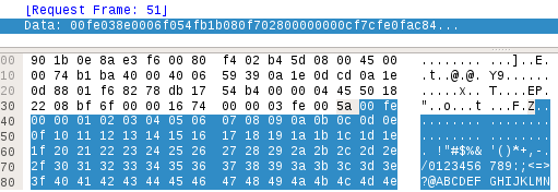
  • UMAS Function Code 0x58 - CHECK_PLC: Check PLC Connection status
  • UMAS Function Code 0x70 - READ_IO_OBJECT: Read IO Object
  • UMAS Function Code 0x71 - WRITE_IO_OBJECT: WriteIO Object
  • UMAS Function Code 0x73 - GET_STATUS_MODULE: Get Status Module

Function codes

Requests and responses

First of all we need to keep in mins that this is a request/response protocol. Function Codes are only sent in request message (generally sent from engineering PCs and SCADAs, but that could also been sent by PLCs themselves if working in a master/slave scenario).

Response do no carry the function code and only carry the response code. Therefore the UMAS packet structure would be the following:

    [ TCP Packet ] - [ Modbus Header ] - [5A] - [ UMAS CODE (16 bit) ] [ UMAS PAYLOAD (Variable) ]

All UMAS Responses have a similar structure as well:

    [ TCP Packet ] - [ Modbus Header ] - [5A] - [ RETURN CODE (16 bit) ] [ UMAS PAYLOAD (Variable) ]

The return code can have two possible values:

 0x01 0xFE - Meaning OK
 0x01 0xFD - Meaning Error


UMAS Function Code 0x01 - INIT_COMM

Request

The request message sent to the PLC has no payload. Therefore the 0x01 request message is as simple as:

       [ TCP Packet ] - [ Modbus Header ] - [5A] - [ 00 01 ] 

or 
       [ TCP Packet ]- [ Modbus Header ] - [5A] - [ 00 01 00]

This is a very simple message (surely the simplest one). It can be seen like this in Wireshark:

If we follow the UNITE protocol documentation, the last "00" could be the "Category Code". However the similarities between both protocols are not frequent, so, this is only a guess.

Note: It's important to note that the UMAS Payload first byte (00 in the previous example), can be different in newer firmware versions. The image example was taken from a Schneider Electric PLC running a 2.10 Firmware version.

This 0x01 message can be sent anytime after the connection is established. It requests some information from the PLC.

Response

The response from the PLC to a 0x01 request depends on wether the PLC is currently "reserved" or not. When a engineer connects to a PLC it automatically "reserves" its use so that no other engineer con connect simultaneoulsy to the PLC. As we will see, this feature can be easily broken.

If the PLC is not currently reserved, the response from the PLC is the following:

As it can be seen, the response informs us about the maximum frame size (bytes "fd 03" - meaning 1022 bytes), the firmware version (bytes "10 02" - meaning firmware version 2.10), followed by 9 bytes that store an internal code and the owner's name size, in this situation, "0".

If the PLC is currently reserved, apart from the whole previous payload, a variable number of bytes is responded, storing the Client_ID Name. The following 0x01 response come from a reserved PLC:

As it can be noted, frame size, firmware version, remains unaltered but the 32-bit internal code has changed and the following fileds have changed. oOners's name has become "OWNED" and owner's name size is now 5 for the 5 letters of "OWNED".

Therefore, the structure of this response message is the following:

       [ TCP Packet ] - [ Modbus Header ] - [5A] - [ Error Code (16bit) ] - [ Max frame Size (16bit) ] - [ Firmware Version (16 bit) ]
       [ Unknown 1 (32 bit) ] - [ Unknown 2 (32 bit) ] - [ Client name length (8 bit) ] - [ Client Name (variable) ]

Note: The PLC Reservation process will be explained later on Function Codes 0x10 and 0x11. The reason why this internal code has changed is explained there.


UMAS Function Code 0x02 - READ_ID

Request

This request allow Schneiders's Unity Pro to discern what's the device it is connecting to. This request can be sent any time during the connection. It's actually the first request sent by Unity Pro int teh connextion start process (which will be explained later).

The request message sent to the PLC has no payload. Therefore the 0x02 request message is as simple as:

       [ TCP Packet ] - [ Modbus Header ] - [5A] - [ 00 02 ] 

For this simplicity, no image will be added showing a 0x02 request.


Response

This is an example of response message:

The response from the PLC allows Unity Pro to know the device name (“BMX P34 2020”) in this case, with this text's length (“0C – 12 in this case), the PLC firmware version (2.10), the Ir (8), the HwId (“06 01 03 01”) and the FwLoc (“00 00 00 00”). We know this information because it is also sent during an FTP connection during a DINF command reply.

Therefore the 0x02 command response has the following structure:

       [ TCP Packet ] - [ Modbus Header ] - [5A] - [ Response Code (16) ] -  [ PLC Family (8) ] - [ PLC Type (8) ] - [ PLC ID (16) ] -  
       [ PLC Model(16) ] -  [ Unknown (16) ] - [ Firmware version (16) ] - [ Patch version (16) ] - [ IR /FWVer (16) ] - [ HwId (16) ] -
       [ FwLOC (16) ] - [ Deive name text length (8) ] - [ Device name (variable) ] - [ # of Memory banks ] - [ Memory bank 1 (64)]
       ...
       [Memory bank N (64 bits) ] 

Explanation:

  • Error Code - As mentioned earlier this 16 bit value can be 0x00FD (Error) or 0x00FE (OK)
  • PLC Family (1 byte). In this case value 05 means Modicon. This information was taken from Unity DLL.
  • PLC Type (1 byte). In this case value 30 means odicon M340, BMX P342020. I don't have a list of PLC types. This information was taken from Unity DLL.
  • PLC ID. (2 bytes). Unknown meaning. This information was taken from Unity DLL.
  • PLC Model (2 bytes). In this case "00 00". This information was taken from Unity DLL.
  • Unknown (2 bytes). 2 bytes which remain unknown. Further investigation will probably shed some light into these values.
  • Firmware Version Internally named "Prod Version". This 16 bit value store in reverse order the firmware version of the PLC 0x1002 means V2.10. Different version values have been checked 0x7002 means v2.70, 0x9002 means v2.90, etc.
  • Patch Version. 16 bit field that informs about the patching level inside a firmware version
  • The Ir 16 bit value has an unknown meaning for me. I know its name from the DINF response during a FTP connection
  • The HwId 32 bit value has an unknown meaning for me. I know its name from the DINF response during a FTP connection
  • The FwLoc 32 bit value has an unknown meaning for me. I know its name from the DINF response during a FTP connection. Probably firmware can be store in different locations in PLC's memory.
  • Device type text length is the number of bytes coming in the next field. In this case "0c" meaning 12 bytes.
  • Next bytes retrieve the PLC type. In this case it's a Schneider Electric's Modicon M340 (internally coded as BMX P342020).
  • # Memory banks. 1 byte that informs how many memory banks the PLC has. The SD Card is considered a Memory bank (that's why in this case the value is 2).
  • Memory bank 1 (8 bytes).
  • Memory bank 2 (8 bytes).

Note: Each memory bank 64 bits fields has the following structure of fields:

       [ Bank type (8) ] - [ Folio (8) ] - [ Status (16) ] - [ Size (32) ] 

Note: Bank Type can be 01 for PLC memory or 04 for SD Card. Other possible value (not tested) would be for Memory bank slots


UMAS Function Code 0x03 - READ_PROJECT_INFO

Request

The read project info request has a 8 bit subcode value meaning which project information needs to be read. The function 0x03 request message has the following structure:

       [ TCP Packet ] - [ Modbus Header ] - [5A] - [ 00 03 ] - [ Subcode ] 

Subcode is an 8 bit value and only values 00, 01, 02, 03 and 04 have been seen. Response

The “00 03 00” request allows Unity to get information about the project that's currently running on the PLC. The response from the PLC is similar to the following:

We still don't know what first 9 bytes mean, but they are sent twice, so this information must be important.

After them, the project creation time and date is sent (again twice), finally the PLC send the version number and the project name with its text's size.

These bytes are also found in the APX file (which will be explained later) in offset 29Ch. You can find a complete explanation of the APX file structure in [this link].

Therefore the response stucture is the following:

       [ TCP Packet ] - [ Modbus Header ] - [5A] - [ Response Code (16) ] -  [ Unknown (9 bytes) ] -  [ Unknown 2 (9 bytes) ] - 
       [ Modification date (8 bytes) ] -  [ Modification date Rep (8 bytes) ] - [ Project Version (16) ] - [ Unknown (16) ] - 
       [ Project Name length (8) - [ Project name (variable) ] 

Note:

The modification date, which is sent twice can be splitted in two fields (modifcation time and modifcation date). Modification time is a reverse translation of values. In the example the 4th (0e) is 14 (or 2 in the afternoon). 24 is 36 in decimal, and 37 y 55 dec. The value 04 is unknown. On regards to the date e0 07 hex is 2016 dec, 02 11 is 11th of february. The date when this logic was uploaded to the PLC

After sending a 00 03 00 request, generally a “00 03 04” request is sent. This request ask for the different Objects stored in the PLC memory. A response like the following is replied:

In this response, after the response code (00FE in this case), come 9 blocks of 12 bytes. with the following structure:

  • Response code (16 bit).
  • # of blocks (8 bits)
  • Block 1 mNb (32 bits). This is the size of the object
  • Block 1 mBase (16 bits). This is the memory base
  • Block 1 mBlock (16 bits). This is the memory block. 0x2a are System bits, 0x2b are system words, 0x2c, etc.
  • Block 1 mOffset (32 bits). This the memory position of the beginning of the block.
  • Block 2 mNb, mBase, mBLock and mOffset. ...
  • Block N mNb, mBase, mBLock and mOffset.

In the example above 9 objects are stored in the PLC (actually only 5). Object 1 is 128 bytes long, starting ofrom position 0 of memory block 0x2a (System bits or coils and with offset 00004. The other object maintain the same structure.

We tried to send requests with another number after “00 03”. Only three of them replied:

  • “00 03 01” → Replied with 60 unknown bytes
  • “00 03 02” → Replied with 77 unknown bytes
  • “00 03 03” → Replied with 67 unknown bytes. Part of the information replied here is the same when requesting a 0x20 message on block 30


UMAS Function Code 0x04 - READ_PLC_INFO (GETPLCSTATUS)

During a Unity pro connection, the “00 04” request is sent every 0.3 seconds. It helps both Unity Pro and the PLC to keep the connection alive.

This is an example of a 0x04 message response from the PLC:

After the response code, the three first bytes are ignored by the PLC (at least in the implementation I reversed). So in the example above, bytes with value "02 86 80" are ignored. The next byte is the number of 32-bit blocks read (in this case 6 blocks). So, the first block is "48 ce 01 01", the second is "20 6e 00 18" and so on.

For every block, values are resversed (First byte last, and last byte first). A variable named mAppliCheckSum is calculated with the sum of the reverse values of blocks 3 and 4 (in the example this checksum would be 0x18906e20+0x18906e20). This is a checksum value used to check if the PLC is legitimate or not.

The following bytes are mostly unknown. The could probably some system bits and words. We still don't know which ones.

What we know is that the 6th byte from the end let us know if the PLC is running or not. In that byte, the bits 7 and 8 let us know if the PLC is on or off. If the PLC is off bits 7 and 8th are 0-1 and if the PLC is on, the bits are 1-0. Therefore if that byte is 1 (like in the example) the PLC is off and if the byte is 2, the PLC is on and running.

Requests “00 01”, “00 02”, “00 03” and “00 04” allow Unity to fill this following Unity's dialog box:


UMAS Function Code 0x06 - READ_CARD_INFO

A request “00 06 00” allows Unity Pro to know what specific SD Card is inserted in the PLC.

The response from the PLC informs Unity about the specific model of SD card and internal info:

After the error code bytes, there are 6 bytes which still remain unknown. After them next byte is the length of the SD Card name. and the following bytes are a null-terminated string with the SD Card name.

This is the structure of this response:

       [ TCP Packet ] - [ Modbus Header ] - [5A] - [ Response Code (16) ] -  [ Unknown (6 bytes) ] - 
       [ SD Card name length (8 bytes) ] -  [ SD Card name (variable) ] 


UMAS Function Code 0x0A - MIRROR/REPEAT

This request may have any kind of sinchronyzation purpose, but it's not very clear to me. This message is sent during the initialization process (which will be explained later) and the PLC just replies with the same payload it was sent in the request.

The following is a UMAS MIRROR request:

...and this is the response received from the PLC.

As it can be seen, the payload is sent back in the next reply from the PLC. The UNITE protocol has a very similar message (named MIRROR, but with a different Function Code). For UNITE, this message purpose is stated to be "to test the correct routing of data between two communicating devices. It is also used for carrying out performance measurements."


UMAS Function Code 0x10 - TAKE_PLC_RESERVATION

This message enables a client (Unity Pro - or an attacker) to partially or completely reserve the functions of a PLC. After this message is sent, if other client (Unity Pro) tries to connect to the PLC (by sending, among others, this message), the PLC responds with an error message.

The following is an example of this message:

The structure of this message is the following:

       [ TCP Packet ] - [ Modbus Header ] - [5A] - [ 00 (by now) ] - [ 10 ] - [ Unknown 1 (32 bit) ] -
       [ Client name length (8 bit) ] - [ Client Name (variable) ]

Once a client reserves a PLC giving a client name, next 0x01 request will respond with the client name given during the reservation process, as can be seen in the following image:

The first message is a 0x01 response message received from the PLC, when it has not been reserved yet. Then a 0x10 TAKE_PLC_RESERVATION message is sent. When another 0x01 message is sent, the PLC responds with the third message in this image. It can be stated, the unknown value passed in the TAKE_PLC_RESERVATION is returned in the 0x01 ID message.


UMAS Function Code 0x11 - RELEASE_PLC_RESERVATION

This request is as simple (“00 11”) as its reply (“00 FE”), which is an OK.

It's used by a client to release the PLC reservation. After this message any other client will be able to reserve the PLC again.


UMAS Function Code 0x12 - KEEP_ALIVE

This request is as simple (“00 12”) as its reply (“00 FE”), which is an OK.

We think it is a simple “I'm still here”, and that it's sent when a period of milliseconds expire with no message sent by Unity.

In other words, it's a keep-alive message.


This is all for today. In part II we'll talk about other interesting Function Codes that can be used to read and write values directly to/from the PLC.